Convert DXF splines to polylines
Open a copy in AutoCAD, choose straight-segment conversion, then compare the saved DXF with the original curve. Keep the original until the result meets your receiving software’s requirements.
For one spline in AutoCAD, set PLINECONVERTMODE to 0, run SPLINEDIT, select the spline, choose P, and enter an integer precision from 0 to 99. Save a separate DXF and check its entities, curve detail, dimensions and open or closed state.
Before converting: confirm the receiving format
A spline is a smooth curve; a straight-segment polyline approximates it with connected lines. Convert when the receiving application requires polylines. Confirm whether it accepts lightweight 2D polylines, legacy polylines or arc segments before choosing export settings.
This guide covers a planar 2D curve. Preserve a copy, note its known dimensions and units, and check whether it is open or closed. Do not flatten 3D geometry or close intentional open paths just to make a file pass a check.
Convert a single spline in AutoCAD
1. Open a copy and inspect the curve
Use Properties to confirm that the selected object is a spline and that it lies in the intended plane. Record a known dimension and the endpoint or closure state before editing.
2. Choose straight segments
Enter PLINECONVERTMODE and set it to 0. Autodesk documents 0 as linear segments and 1 as arc segments. Check the current setting rather than assuming a default; arc-containing polylines are outside TraceDXF’s checked subset.
3. Run SPLINEDIT
Enter SPLINEDIT, select the spline, then choose P (Convert to Polyline). The instructions follow Autodesk’s AutoCAD 2025 help and support article updated June 5, 2025; they have not been reproduced in a local AutoCAD session for this guide.
4. Choose precision and compare
Enter an integer from 0 to 99. Increase it if the approximation loses needed curve detail, then compare again with the original. This setting is not a millimeter tolerance or a fixed vertex count. Higher detail can increase the geometry and processing cost.
5. Save a separate DXF and reopen it
Use SAVEAS with a DXF version supported by the receiver. Inspect the saved entity types, scale, endpoints, closure and deviations. Do not assume choosing R12 preserves LWPOLYLINE: Autodesk warns that saving splines in R12 can create 3D polylines and affect other drawing data.
Compare two self-made approximations
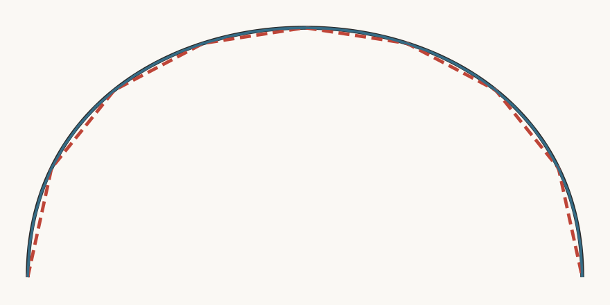
The downloadable source is one open cubic spline, 100 × 45 mm. Our script creates an 8-segment polyline with 9 vertices and a 32-segment polyline with 33 vertices. Both retain the same endpoints, open state and bounds; neither contains arc bulges. These are self-made engineering examples, not AutoCAD command exports or examples of particular precision settings.
Across 100,001 curve samples, the largest measured distance to the coarse polyline is about 1.1523 mm; to the fine polyline, 0.0732 mm. Conservative mathematical bounds for this subdivision are 1.3667 mm and 0.0855 mm. Sampling alone does not prove an exact maximum. Neither file has been imported into AutoCAD or LightBurn for this comparison; choose a tolerance for your own task.
Check the saved DXF before moving on
The DXF checker reports declared units, supported entity counts and bounds. TraceDXF checks only ASCII 2D LINE and straight-segment LWPOLYLINE geometry; it does not convert SPLINE. Unsupported SPLINE, ARC, CIRCLE, legacy POLYLINE or nonzero bulges remain unchecked. A parser result does not prove receiving-software compatibility.
Use DXF to SVG only after the saved geometry falls within that same subset. For a scale discrepancy, follow the DXF wrong-size guide; for an Inkscape export workflow, follow the SVG-to-DXF guide. Keep software conversion and unit troubleshooting as separate checks.
Common preparation questions
Which precision value should I use?
No value guarantees a particular millimeter error. Choose a starting integer within 0–99, compare the result against the original, and increase detail only as needed. Inspect tight bends, dimensions and the receiving application’s requirements.
Can TraceDXF convert my SPLINE DXF?
No. Convert the spline in software that supports it first. TraceDXF’s current checker and DXF-to-SVG tool cover ASCII 2D LINE and straight-segment LWPOLYLINE, with known units and explicit limitations.
Can I convert several splines at once?
Autodesk documents PEDIT → M (Multiple), select the splines, confirm Y for conversion, enter precision 0–99, then Esc. Select them during PEDIT rather than beforehand. Inspect each result and the saved file; this batch workflow has not been locally reproduced for this guide.
Sources and verification
Sources: Autodesk’s single-spline conversion article (June 5, 2025), AutoCAD 2025 conversion and curve-detail help, SPLINEDIT command reference, and PLINECONVERTMODE reference. The downloadable measurements describe our generated engineering files, not Autodesk software output.