SVG vs DXF: choose the format for your next step
Start with what the receiving application needs, then check the geometry and size it actually imports.
Choose SVG for browser display, graphic editing and workflows that need SVG styling. Choose DXF when the receiving CAD or cutting software specifically needs a supported DXF version and entity set. Both can carry vector geometry; neither guarantees the right physical size or a ready-to-cut drawing.
Compare the formats
| Requirement | SVG | DXF |
|---|---|---|
| Browser graphics | Native browser rendering for paths, fills and strokes. | Usually requires a viewer or conversion for a browser preview. |
| Appearance | Can represent fills, strokes, text, gradients and embedded images. | Can represent geometry, layers and other CAD data; transferring SVG styling depends on the exporter and receiver. |
| Curves | Paths can include Bézier curves, arcs and straight segments. | Entity types can include lines, polylines, arcs and splines; support varies by version and importer. |
| Physical size | Width/height units, viewBox and transforms affect interpretation. A pixel canvas is not an intended cutting size. | Coordinates and unit metadata/import settings must agree. A .dxf extension does not ensure millimeters. |
| Common next step | Web display or graphic/vector editing; cutting when the receiver supports the file correctly. | Exchange with CAD or cutting software that asks for DXF. |
Choose from the job you need to finish
You need an editable logo or web graphic
Use SVG when you need scalable paths and graphic appearance in an SVG-capable editor or browser. Check for embedded images: an SVG can still contain a PNG or JPG rather than traced paths.
Your receiving program requests DXF
Ask which DXF version and entities it supports. Export that subset and check a known dimension after import. Switching the file extension or choosing DXF alone does not repair open contours or duplicate geometry.
Both formats are accepted for cutting
Try the same simple drawing in both formats. Compare physical size, orientation, holes and separate pieces. Choose the one the receiver reads correctly with the least manual repair; do not treat one format as universally better.
What TraceDXF puts in each file
TraceDXF creates monochrome outline geometry from PNG/JPG. Its SVG uses path geometry and an evenodd fill rule for holes. Its DXF uses closed LWPOLYLINE contours in an AutoCAD 2000 file with millimeter coordinates. These are this tool’s choices, not limits of SVG or DXF as formats.
SVG can use a source-pixel canvas or a user-set physical size; DXF requires a physical size. The current tool does not preserve a color illustration, generate toolpaths, or convert an existing SVG/DXF file.
Compare the same outline in both files
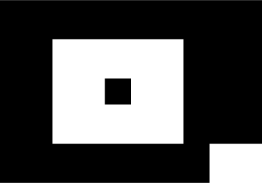
The self-made calibration pair has 100 × 70 mm outer bounds, a 50 × 40 mm hole, a 10 × 10 mm island and a bottom-right notch. Both original TraceDXF files were measured at 100.000 × 70.000 mm in LightBurn 2.1.04 Core under the recorded conditions. This result applies to this fixture and version; no machine was connected.
Before you use either file for cutting
Measure the imported drawing, not the document page. Inspect unwanted open paths, duplicated edges, lost holes and misplaced parts. A visible fill is not a cutting instruction, and an outline file is not a machine toolpath.
If you already have a vector SVG and need DXF, use an SVG-capable editor such as Inkscape. If you start with a monochrome image, trace the image first. Each task has its own guide below.
Sources and verification
General SVG capabilities follow the W3C specification; DXF entities and versions follow Autodesk documentation. The sample result comes from the linked LightBurn calibration record, not from a blanket compatibility claim.