Convert an existing AutoCAD ellipse to a polyline
Changing PELLIPSE affects ellipse creation. An existing true ellipse needs a separate conversion workflow and an output check.
For an existing true ellipse, Autodesk documents a selected-object R12 DXF export and reinsertion workflow. Work on a copy and inspect the resulting entity: an R12 result can be an open 3D polyline, not the closed 2D LWPOLYLINE your receiver needs.
Distinguish an existing ELLIPSE from a new polyline ellipse
Inspect the selected object in Properties or LIST. A true ELLIPSE is not a SPLINE and does not use the SPLINEDIT conversion taught in the spline guide. PELLIPSE=0 creates true ellipses; PELLIPSE=1 creates polyline representations for subsequent ELLIPSE operations.
Setting PELLIPSE=1 alone does not rewrite an existing ellipse. First confirm whether the receiver accepts true ELLIPSE objects; preserving that object may be preferable when conversion is unnecessary.
Follow the documented R12 roundtrip on a copy
These steps summarize Autodesk’s documented workflow, checked on 2026-10-15. They were not reproduced in a locally installed AutoCAD version for this guide. Keep the original drawing and record your version and settings.
Copy the drawing and identify the object
Record the true ellipse’s axes, dimensions and units in a working copy. Confirm that you intend a full ellipse rather than an open ellipse arc.
Record and set the variables
Note the current PELLIPSE and PLINETYPE values. Autodesk’s procedure uses PELLIPSE=1 and PLINETYPE=0 before the interchange steps; this is not a standalone conversion command.
Export only the selected ellipse
Use Save As or DXFOUT, choose AutoCAD R12/LT2 DXF, and enable Select Objects under Tools → Options → DXF Options. Save to a separate file and select the ellipse.
Replace only the working-copy object
After saving the export, remove the source ellipse only from the working copy. INSERT the DXF at 0,0 with on-screen placement disabled and Explode enabled, following Autodesk’s procedure. Preserve the original drawing separately.
Inspect the actual result, not its filename
Check Properties for entity type, intended closure, elevation and dimensions. A polyline label alone does not establish a planar closed LWPOLYLINE. Reopen the saved delivery file and inspect it in the intended receiver.
Restore the drawing variables
Restore the recorded PELLIPSE and PLINETYPE values if you do not want later drawing operations to use the changed settings. Keep the converted copy and original as separate files.
Do not treat R12 as a lossless compatibility switch
Autodesk separately documents ellipses becoming unclosed 3D polylines when saved as R12 DXF. That result is outside this site’s strict 2D subset. Do not silently discard elevation or close every object: an intended ellipse arc must remain open.
If the receiver supports true ellipses, a newer DXF version may avoid the legacy conversion. If it requires a 2D polyline, use suitable editing/conversion software and verify the resulting geometry; saving under a newer filename does not itself solve that requirement.
Compare two known 100 × 60 mm approximations
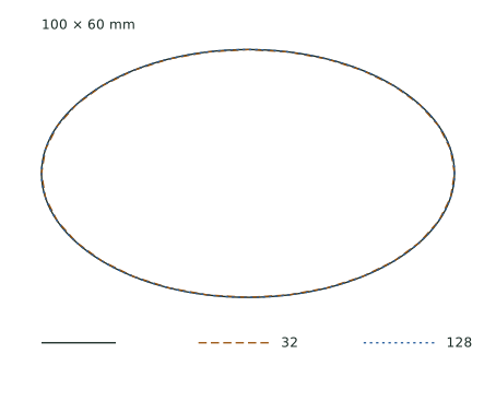
These self-created files start from an analytic ellipse with 50 mm and 30 mm semi-axes. The 32- and 128-vertex files are closed, straight-segment 2D LWPOLYLINEs sampled at equal parameter intervals. They are generated engineering references, not AutoCAD exports or R12 roundtrip results.
The table gives conservative chord-deviation upper bounds, rounded upward and including coordinate serialization rounding. The analytic formula is 50 × (1 − cos(π/N)) mm; it is not a measured maximum, an AutoCAD precision setting or a machining tolerance. More vertices do not replace checking your own receiver’s requirements.
| Vertices / segments | Bounds (mm) | Conservative deviation upper bound (mm) |
|---|---|---|
| 32 | 100 × 60 | 0.240764 |
| 128 | 100 × 60 | 0.015060 |
Check the delivery copy without losing its limits
The source ELLIPSE is readable by the independent parser but outside this site’s checker subset; no supported geometry is not a corrupt-file verdict. The two generated LWPOLYLINE references pass that subset check. Their parser result says nothing about your AutoCAD export.
For your own file, inspect the complete entity inventory and unresolved warnings, then verify units, bounds and the intended open/closed state. Use the blank-import guide for missing content and the size guide for scale differences. No external-software compatibility or machining result is claimed by these examples.
Sources and verification
The workflow and R12 warning come from the linked Autodesk references. The downloadable geometry and bound derivation are project-created CC0 materials dated 2026-10-15. No native AutoCAD operation, external import or machine test was performed for this guide.