Join lines into a polyline in AutoCAD without closing the wrong gap
Connect the intended segments first. Add a closing edge only when it belongs in the design.
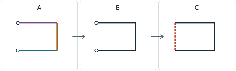
For a chain of lines, use PEDIT → Multiple, select the intended objects, accept conversion if prompted, then Join. Check endpoints and the joining method before using a fuzz distance. Join does not mean Close: Close adds a segment between the first and last vertices.
Check the intended contour before joining
Keep a separate original. Identify the source object types, drawing units, endpoint positions and Z/elevation. Decide whether the result should remain an open chain or become a closed boundary; text, splines and true ellipses require their own preparation.
A line, polyline and block are different objects even when they look connected. AutoCAD JOIN is source-type dependent: a source LINE joins collinear lines, while other combinations can produce different object types. This guide uses PEDIT for a multi-segment polyline task.
Use PEDIT Multiple and Join on a copy
Select only the intended chain
Run PEDIT, choose M (Multiple), select the intended lines or polylines, and press Enter. If asked whether to convert lines to polylines, choose Yes. Prompts vary with the version and PEDITACCEPT setting.
Join exact endpoints first
Choose Join. For endpoints that actually touch, start with a fuzz distance of 0. Inspect the result rather than assuming an unchanged appearance means the objects became one.
Measure a real gap before increasing tolerance
If joining fails, inspect both endpoints at adequate coordinate precision and check their Z/elevation. A larger fuzz distance is justified only when it covers an intended connection without capturing a different nearby feature. The sample’s 0.04 mm gap is a known input, not a recommended setting for all drawings.
Check how the join changes geometry
PEDIT Jointype offers Extend (extend or trim), Add (insert a straight connecting segment), and Both (extend or trim where possible, otherwise add a segment). Record the chosen method and compare the changed endpoints and dimensions.
Keep an open result when that is the task
Exit PEDIT and inspect object count, entity type and the resulting path. A connected polyline can still be intentionally open. Preserve openings, holes and separate parts that belong to the design.
Close only a verified boundary
If the intended boundary needs a final edge, select that polyline in PEDIT and choose Close. Inspect the new first-to-last segment. Save a separate delivery file, reopen it, and recheck dimensions, entity types and closure in the receiving application.
Use different checks for a failed join and an open contour
An apparent meeting point may hide a gap or different Z values. Do not flatten a design or erase elevation only to make a command succeed unless that projection is an intended design change. Noncoplanar linear objects can produce 3D results in CAD; TraceDXF does not project them silently into XY.
A polyline can also contain arc bulges. Joining LINE and ARC objects does not guarantee a straight-segment LWPOLYLINE in this site’s subset. Keep unsupported-object warnings visible and check the complete file in suitable software.
Compare five small DXF references
These project-authored files are engineering references, not AutoCAD PEDIT/JOIN results. The first four have a 100 × 70 mm XY boundary. The open reference deliberately has a 70 mm terminal separation; Close adds that 70 mm edge. The gapped LINE file has only one internal gap of 0.04 mm.
The noncoplanar reference preserves an endpoint at Z=5 mm. Its full 3D coordinates are recorded separately; a flat contour boundary is not applicable. The checker excludes that line and blocks SVG export, so a supported portion cannot be mistaken for the complete design.
| Sample | Entity inventory | Known condition | Flat XY bounds (mm) |
|---|---|---|---|
| Touching separate lines | 3 LINE | Open chain; 2 touching joins | 100 × 70 |
| One 0.04 mm internal gap | 3 LINE | One internal gap; intended ends remain open | 100 × 70 |
| Open polyline reference | 1 LWPOLYLINE | 4 vertices, 3 segments; open | 100 × 70 |
| Closed polyline reference | 1 LWPOLYLINE | 4 vertices, 4 segments; closed | 100 × 70 |
| Noncoplanar lines | 3 LINE | Endpoint Z=5 mm; not a flat XY contour | Not applicable to the complete 3D geometry |
Check the delivery file with its actual unit and entity contract
The DXF checker reports supported geometry in its declared drawing unit. DXF-to-SVG converts known source units to physical millimeters; if units are unknown, choose the actual source unit explicitly. No unit is inferred from how large a shape looks.
TraceDXF does not join, close or repair your DXF. It accepts only its documented straight LINE/LWPOLYLINE subset in the default XY plane. Keep the original and confirm the full result in the application that will use it.
Sources and verification
The steps summarize the linked Autodesk documentation checked on 15 October 2026. The CC0 downloads are deterministic project geometry, not a native AutoCAD reproduction, LightBurn import or machining test.