Convert a stroke to a path in Inkscape without losing its width
A thick SVG stroke is a style around a center path. When the receiver needs the visible area as geometry, convert that stroke into its boundary and check the endpoints, corners and holes.
Set the intended stroke width, cap and join, select the object, then choose Path → Stroke to Path. The stroke becomes a filled outline. Keep the original center path when the next task needs one drawing or engraving line.
Decide whether you need a center path or an area boundary
A 6 mm stroke around a line still has a center path with two endpoints. A receiver that imports only path coordinates can retain the centerline while ignoring its visual width. Stroke to Path turns that displayed width into the outer boundary of a filled area.
Use the center path for a single line operation; use the boundary when the intended object is the whole thick region. Two separated edges of an outlined stroke are meaningful boundaries, not automatically duplicate lines. Converting does not set engraving mode, kerf or machine parameters.
Convert and inspect in five steps
Keep the source center path
Save an editable original and work in a copy. Record whether the input is open or closed. Avoid leaving a hidden duplicate source in the exported selection.
Set width, endpoints and corners
Open Object → Fill and Stroke and inspect Stroke Style. Set the actual width and choose the intended cap and join. Butt caps stop at the endpoints; square and round caps extend beyond them. A miter corner can project farther than a bevel or round corner. Check dashes or markers separately if present.
Convert the selected stroke
With the Selector, select the intended stroked object and choose Path → Stroke to Path. For this guide’s simple cases, start with no fill and no markers. Official Inkscape 1.0 notes describe a group of stroke, fill and marker components when those extras are present; inspect the result instead of assuming one object.
Inspect the new boundary
Use the Node tool and compare the filled result with the source. Check cap extent, corner shape, closure and any inner hole. An open centerline becomes a closed area boundary; a closed stroked loop has outer and inner boundaries. Remove an unwanted extra stroke from the resulting filled shape before comparing its visible bounds.
Save and compare the outline size
Save a separate SVG, reopen it and measure the resulting area. Compare against the stroke’s visible bounds, not just the original centerline bounds. Keep the two legitimate boundaries of a closed band together; deleting the inner one changes the filled area.
Compare four width and boundary cases
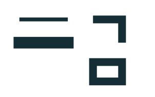
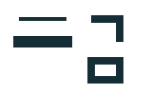
The engineering fixtures dated 2026-10-14 use an 80 × 50 mm page. A 25 mm horizontal centerline with 2 mm butt stroke becomes a 25 × 2 mm area. The same length with 6 mm square stroke becomes 31 × 6 mm. A 4 mm right-angle miter stroke has 17 × 14 mm bounds. The closed rectangle’s outer bounds are 19 × 14 mm and its hole is 11 × 6 mm.
The input has four stroked paths; the reference has four filled path elements and five closed contours, with no remaining stroke width. The outlines are analytically constructed from axis-aligned offsets, not exported by Inkscape. The record includes the source parameters, bounds and file hashes; it demonstrates structure and dimensions without claiming native software or machine compatibility.
Export the geometry your receiver expects
For a supported straight-segment SVG, the SVG→DXF tool transfers the boundary coordinates. It does not transfer SVG fill as a machining operation or preserve a centerline’s visual stroke width. Curved caps, joins or Bézier outlines may fall outside the strict subset; use the Inkscape export guide for those files.
If a shape fails to fill later, check closure and compound-path holes before deleting apparent duplicate edges. The outline-versus-centerline guide helps choose the geometry; the LightBurn shape diagnostic helps separate closure, display and overlap symptoms. Neither replaces checking the resulting file in its intended receiving software.
Common preparation questions
Why did Stroke to Path make two lines?
A closed stroked loop is a band with an outer boundary and an inner boundary. Those contours describe different edges. A cutting operation may follow both, so choose the original center path if your task needs only one line.
Will Object to Path preserve stroke width in DXF?
Object to Path converts the underlying object to path geometry; a stroke can still be styling around that geometry. Use Stroke to Path when the visible width must become an actual boundary, then inspect what the DXF exporter produced.
Why is my converted shape larger than the center path?
The stroke extends around the center path. Square and round caps add half the stroke width beyond an open endpoint, and joins can extend corners. Compare the converted outline with the visible stroke rather than the center coordinates.
Sources and verification
The official Inkscape Beginners’ Guide explains stroke width, caps, joins and path nodes. The official 1.0 release notes describe Stroke to Path and its treatment of fill and markers. The steps are source-grounded; the downloadable offsets are engineering-generated, with no local native Inkscape reproduction.