Outline vs centerline tracing
A thick stroke can become two boundary paths when you trace its filled area. Use this comparison to choose the geometry your editor or fabrication workflow actually needs.
Choose an outline when the filled boundary is the intended shape. Choose a centerline workflow when one path through a stroke is required, then create and verify it in software that supports centerline or medial-axis tracing; this project’s browser tool produces filled outline contours only.
Choose the geometry before tracing
Raster tracing sees foreground area. A thick line therefore has two edges, so a filled-region trace naturally returns an outline around the stroke rather than one path down its middle.
The comparison below is a self-made explanatory fixture, not an export from a target machine or a claim that every editor will produce the same nodes. Decide whether the receiver needs an area boundary or a single stroke path before changing thresholds.
| User goal | Geometry to inspect | Boundary |
|---|---|---|
| Cut the outside of a filled mark | Closed outer and inner boundaries, with holes preserved | An outline is expected; a centerline would change the cut shape |
| Engrave or plot one stroke path | One open or closed path located through the stroke | Filled outline tracing cannot infer the intended centre automatically |
| Use a logo or silhouette as an area | Check the perimeter, holes and separate islands | Do not remove one of two boundaries just because it looks duplicated |
| Send geometry to another editor | Confirm path type, closure, units and stroke/fill semantics | The receiving application’s centerline implementation remains unverified here |
Decide and verify in five steps
Describe the physical action
Write down whether a tool should follow an area boundary or one path through a drawn stroke. The answer determines the geometry, not the file extension.
Inspect the source stroke
Check whether the source has meaningful width, holes, islands or open endpoints. A thresholded raster does not contain an explicit centreline label.
Choose an appropriate method
Use filled outline tracing for area shapes. For centerlines, use an editor or tracing method that documents centerline, skeleton or single-line output; this page does not pretend to perform that conversion.
Open the result as geometry
Select nodes or paths in the receiving editor. Count the expected boundaries, inspect open versus closed ends, and confirm that an embedded bitmap has not been mistaken for a vector.
Check scale and handoff semantics
Measure physical bounds, units, stroke/fill interpretation and whether the receiver follows a stroke or its outline. A visually similar preview is not enough evidence.
A self-made comparison fixture
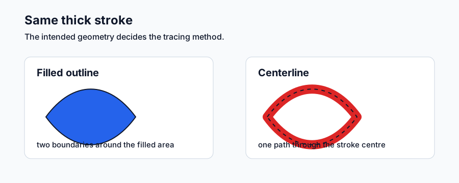
The diagram keeps the same loop-like stroke in two explanations: an area outline has boundaries around filled geometry, while a centerline is a single conceptual path through the stroke. It is a teaching diagram, not a software export or machine result.
Use the diagram to name the expected result before opening a file. The project’s local raster converter can verify filled contours, dimensions and exports, but it does not generate centerline paths.
Check the result before delivery
| Question | Evidence to look for |
|---|---|
| Did I choose an area or a stroke path? | The intended physical action is written down and matches the path geometry. |
| Are the boundaries expected? | Outline work has the correct closed contours; centerline work has the intended single path and endpoints. |
| Did the receiver preserve semantics? | Stroke/fill, open/closed state, holes, islands and units are explicit after import. |
| Am I claiming more than the evidence? | Centerline output is labelled as external or unverified unless the exact editor, version and file are recorded. |
Continue with the matching workflow
Use the method guide for filled-outline tracing, the Inkscape guide for a complete bitmap trace, and the logo guide when the input is a simple monochrome mark. For centerline output, follow the documentation of a suitable external editor and keep its result separate from this project’s outline exports.
Sources and verification
The geometry distinction follows the Inkscape tracing documentation and the project’s self-made comparison diagram. The page explains a method choice; it does not report a centerline software test, target-device import, or universal compatibility.