How to turn a PNG or JPG into real SVG paths
Start with the result you need: a filled outline, layered color artwork, an editable source vector or a single centerline. The right method depends on the image and the receiving software.
For a high-contrast monochrome shape, trace the filled regions and confirm that the saved SVG contains editable paths rather than an embedded bitmap. Use a multicolor tracing workflow for separated color layers, an SVG editor for an existing vector, and a centerline workflow when one path down the middle of a stroke is the actual goal.
Choose by input and intended result
Image-to-SVG is not one operation with one correct output. A filled outline follows the visible boundary of a region; a centerline follows the middle of a stroke. Those paths can lead to different files and different results in the receiving application.
This page helps you choose the branch before you trace. It covers the decision and the checks that prove the result; the linked Inkscape guide supplies the full menu sequence for the monochrome outline branch.
| Starting point | Use this workflow | Check before delivery |
|---|---|---|
| Dark logo, icon or silhouette on a light background | Single-scan brightness or threshold tracing | Closed filled paths, holes and small bridges |
| Illustration with separate colors | A multicolor tracing workflow in a suitable editor | Layer boundaries, overlap and whether the receiver supports color |
| Thick line where the center is the intended toolpath | A centerline tracing workflow | One open or closed center path, not two outline edges |
| An SVG that already contains vector objects | Inspect and edit the existing paths; do not raster-trace it again | No embedded image is being mistaken for vector geometry |
Make the choice in five checks
Name the receiving task
Decide whether the next application needs a filled cutting outline, separate color regions, an editable graphic or a single centerline. A file extension cannot make that decision for you.
Inspect the source image
Look for contrast, JPEG ringing, transparent edges, holes, thin bridges and separate components. Crop unrelated content before tracing; missing pixels cannot be recovered later.
Pick the matching trace mode
Use a single-scan threshold for one-color filled regions. Choose a multicolor mode only when the layers are useful to the receiving workflow. Choose centerline tracing for a true middle path; thresholding a thick line normally returns both edges.
Prove that the result is geometry
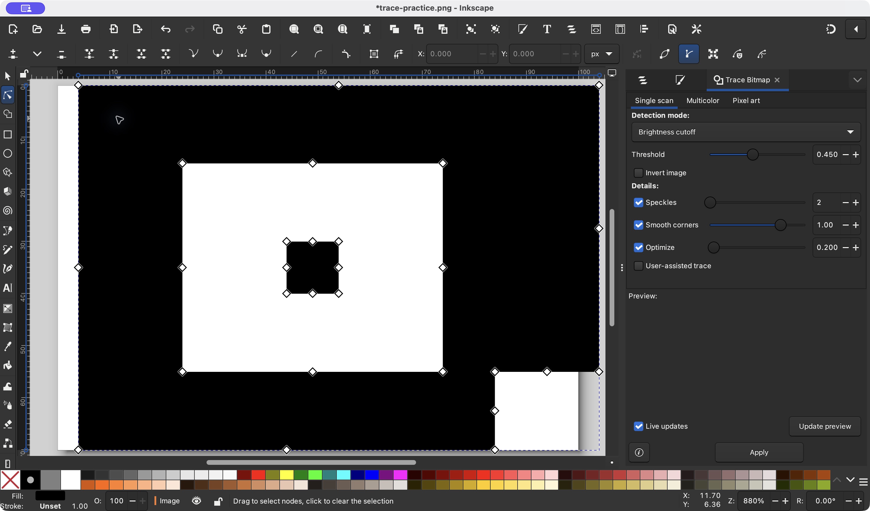
Select the result with a node tool, move it away from the source image and reopen the saved SVG. An SVG can still contain an image element, so the filename alone is not proof of vectorization.
Check the delivery contract
Measure the intended drawing bounds, inspect holes and independent parts, and confirm the receiver supports the path and unit choices. Set a physical size separately when the file is for cutting.
A monochrome path example
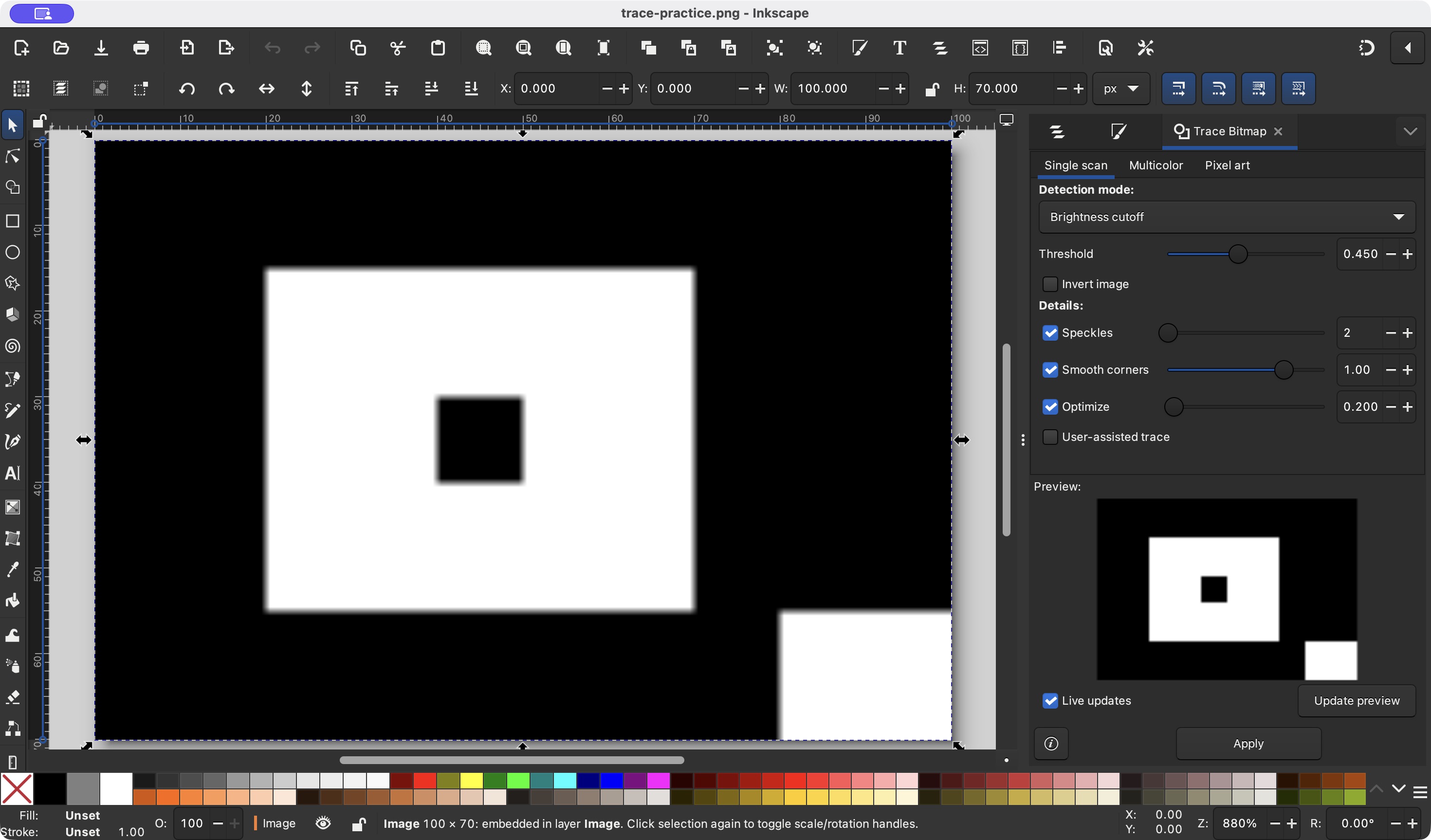
The linked project fixture is a self-made 100 × 70 pixel monochrome drawing with a hole, an island and a lower-right notch. Inkscape 1.4.4 produced a compound editable path after a single-scan trace and removal of the bitmap.
This example demonstrates the outline branch only. It does not test multicolor tracing, centerline extraction, arbitrary photos or fabrication equipment. The SVG keeps a pixel page and is not a 100 mm cutting file.


Check the SVG before handing it off
| Question | Evidence to look for |
|---|---|
| Is it a real vector? | A node tool selects paths and the file has no unwanted image element. |
| Did the topology survive? | Holes stay empty, bridges remain connected and independent parts remain separate. |
| Is the method correct? | A thick stroke is not silently being treated as a centerline, and color layers are not being flattened by the receiver. |
| Is the scale explicit? | The physical bounds and units are set or measured for the receiving application; pixel canvas size is not used as a cutting claim. |
Continue with the matching workflow
For a simple monochrome PNG, use the local PNG-to-SVG tool and inspect its binary and outline previews. For the complete Inkscape menu sequence, use the dedicated tracing guide. Use the format guide when the receiving application accepts both SVG and DXF.
Check whether the SVG contains an embedded image
SVG is a container format: it can hold editable paths, an image element, or both. A file that ends in .svg is therefore not proof that the pixels were converted into geometry.
Use the editor's object or layer panel, then reopen the saved file. The check should answer whether the visible result survives after the bitmap is hidden and whether the remaining objects are the ones the receiving task can use.
| Inspection | Evidence |
|---|---|
| Open the object or XML panel | Vector objects expose path, circle, rect or similar geometry entries. |
| Search for an image element | An image element or data URL identifies bitmap content that still needs a separate decision. |
| Hide or move the bitmap | The traced paths remain visible and selectable without the source image underneath. |
| Reopen the saved SVG | The same geometry and intended holes remain after save and reopen; a preview alone is not enough. |
Sources and verification
The method split follows the Inkscape tracing documentation and the project’s fixed browser comparison. The screenshots, files and measurements are engineering evidence for the recorded fixture; they do not certify arbitrary images, centerline output or target-software compatibility.